What is NSX-T, and how to build a Home Lab

Let me start by saying that I've been a big NSX fan ever since it came to the market. I was one of the first CCIEs to get to the VCIX-NV (VMware Certified Network Virtualization Expert). It provides a single point of management of your Network and Security within the entire VMware environment, and it supports APIs, enabling us to finally include Networks into the DevOps philosophy. Olé! Right? Check out the Blog Map for more of my NSX posts.

While NSX is an awesome product, there are 3 things that I haven't liked, from the bare beginning of the product:

  1. Management: You can only manage NSX from your vSphere Web Client. Not great UX, a Web Client Plugin that VMware never really got a decent level… No wonder most of VMware admins prefer the vSphere Thick client (not an option for Network and Security admins).
  2. NSX only supports ESXi as a hypervisor. It's the best one, I'll admit, but todays Cloud requires MORE flexibility, not less…
  3. No way of managing the Physical Network (Underlay). Regardless of the Overlay Networking philosophy, and the fact that NSX would work perfectly over most low latency high throughput Data Center Fabrics, I've seen cases where this was a deal breaker.


I'm happy to say that VMware actually addressed 2 of my 3 complains with NSX-T:

  • You can now manage NSX using a separate GUI interface, all HTML5!!! Finally!
  • NSX-T supports KVM, and will potentially support bunch of other integrations… and yeah, CONTAINERS!!!


No wonder I wanted to try it as soon as it was available for download. So I did… and wow, was that a pleasant surprise!!! The installation process is just so clean and nice, I was truly impressed. In this post I'll just cover the Manager and Control Cluster part, and in my next post I'll proceed with the Hypervisor integration and the Data Plane.

Before I proceed with the deep technical stuff, here are a few facts to help you fall in love with NSX-T:

  • It's unofficially called "Transformers" because different releases have different Transformers names.
  • The NSX license is unique. This means that you can buy the license, and use it in NSX-V (vSphere integrated version) or NSX-T.
  • It supports Containers!!! Yes, I'm aware I always end this with 3 exclamations.
  • NSX-T is too cool for VxLAN, so it's using a new, and cooler GENEVE* protocol.


*VXLAN and NVGRE headers both include a 24-bit field. STT specifies a 64-bit field. None requires modifying or replacing existing switches and routers, although some equipment vendors have developed hardware assists to increase the efficiency of one or more of the solutions. Now a new network virtualization standard has emerged -- Generic Network Virtualization Encapsulation (GENEVE) -- that promises to address the perceived limitations of the earlier specifications and support all of the capabilities of VXLAN, NVGRE and STT. Also… very few actually use the "basic" VXLAN implementation, most vendors, like Cisco and VMware use the "on steroid" improved versions, which makes them mutually non compatible. Many believe GENEVE could eventually replace these earlier formats entirely. More details here.


NSX-T Installation

Step 1: Install a NSX Manager and 3 NSX Controllers as OVA files to vCenter or KVM. You will need 4 mutually routed IP addresses.

If you need instructions on how to deploy an OVA in your vCenter, you're at the wrong blog :)

Step 2: SSH into NSX Manager and all of the Controllers, and do a manual Joining process:

NSX Manager

NSX CLI (Manager 2.1.0.0.0.7395503). Press ? for command list or enter: help
nsx-t-manager>
nsx-t-manager> get certificate api thumbprint
3619a99a934ddacf06792ea0cf0566c1d49223ac5117a73d95c31e5c482ef868

nsx-t-manager>


Controllers 

(repeat this on all 3 controllers, regardless that you dont have the Control Cluster built):

NSX CLI (Controller 2.1.0.0.0.7395493). Press ? for command list or enter: help
nsx-t-controller-1>
nsx-t-controller-1>
nsx-t-controller-1> join management-plane NSX-Manager username admin thumbprint 3619a99a934ddacf06792ea0cf0566c1d49223ac5117a73d95c31e5c482ef868
% Invalid value for argument : NSX-Manager
: IP address of NSX manager with optional port.

nsx-t-controller-1> join management-plane 10.20.41.120:443  username admin thumbprint 3619a99a934ddacf06792ea0cf0566c1d49223ac5117a73d95c31e5c482ef868
Password for API user:
Node successfully registered and controller restarted

nsx-t-controller-1>
nsx-t-controller-1> get managers
- 10.20.41.120     Connected

nsx-t-controller-1>

Verify on the NSX Manager:


nsx-t-manager> get management-cluster status
Number of nodes in management cluster: 1
- 10.20.41.120     (UUID 4207150A-9BB0-6283-181E-AAB3924321BF) Online

Management cluster status: STABLE

Number of nodes in control cluster: 1
- 10.20.41.121     (UUID cf4e1847-508e-4a73-96df-c2311f96a55b)

Control cluster status: UNSTABLE


Now other 2 Controllers:

nsx-t-controller-2> join management-plane 10.20.41.120:443  username admin thumbprint 3619a99a934ddacf06792ea0cf0566c1d49223ac5117a73d95c31e5c482ef868
Password for API user:
Node successfully registered and controller restarted

nsx-t-controller-3> join management-plane 10.20.41.120:443  username admin thumbprint 3619a99a934ddacf06792ea0cf0566c1d49223ac5117a73d95c31e5c482ef868
Password for API user:
Node successfully registered and controller restarted


nsx-t-manager> get management-cluster status
Number of nodes in management cluster: 1
- 10.20.41.120     (UUID 4207150A-9BB0-6283-181E-AAB3924321BF) Online

Management cluster status: STABLE

Number of nodes in control cluster: 3
- 10.20.41.121     (UUID cf4e1847-508e-4a73-96df-c2311f96a55b)
- 10.20.41.122     (UUID 4517abc2-5244-4327-a3c8-739ac18b0fd7)
- 10.20.41.123     (UUID 22ab7f0a-02a4-42b0-93b0-f8cce56c4200)

Control cluster status: UNSTABLE

Note that the Control Cluster is still UNSTABLE. Let´s fix this…


Step 3:  Build the control cluster:

After installing the first NSX Controller in your NSX-T deployment, you can initialise the control cluster. Initialising the control cluster is required even if you are setting up a small proof-of-concept environment with only one controller node. If you do not initialise the control cluster, the controller is not able to communicate with the hypervisor hosts.

Lets first make a Controller Cluster, while we only have 1 controller:
set control-cluster security-model shared-secret

nsx-t-controller-1>
nsx-t-controller-1> set control-cluster security-model shared-secret
Secret:
Security secret successfully set on the node.

nsx-t-controller-1> initialize control-cluster
Control cluster initialization successful.

nsx-t-controller-1> get control-cluster status verbose
NSX Controller Status:

uuid: cf4e1847-508e-4a73-96df-c2311f96a55b
is master: false
in majority: false
This node has not yet joined the cluster.

Cluster Management Server Status:

uuid                                 rpc address          rpc port             global id            vpn address          status
f0c3fc47-b07c-4db2-9b9d-f4df7ad2aa62 10.20.41.121         7777                 1                    169.254.1.1          connected

Zookeeper Ensemble Status:

Zookeeper Server IP: 169.254.1.1, reachable, ok
Zookeeper version: 3.5.1-alpha--1, built on 12/16/2017 13:13 GMT
Latency min/avg/max: 0/0/14
Received: 212
Sent: 228
Connections: 2
Outstanding: 0
Zxid: 0x10000001d
Mode: leader
Node count: 23
Connections: /169.254.1.1:40606[1](queued=0,recved=204,sent=221,sid=0x1000034b54f0001,lop=GETD,est=1514475848954,to=40000,lcxid=0xc9,lzxid=0x10000001d,lresp=3485930,llat=0,minlat=0,avglat=0,maxlat=8)
 /169.254.1.1:40652[0](queued=0,recved=1,sent=0)

nsx-t-controller-1>


To make this "STABLE", create a control CLUSTER, and associate the other Controllers to the NSX Managers. Once you do:

nsx-t-controller-2> set control-cluster security-model shared-secret secret SHARED_SECRET_YOU_SET_ON_CONTROLLER_1
Security secret successfully set on the node.

nsx-t-controller-2> get control-cluster certificate thumbprint
ef25c0c7195907387874ff83c0ce0b1775c9a190c2b27c82f9ad1db3da279c3d


Once you have those, go to the MASTER Controller, and join the other Controllers to the Cluster:

nsx-t-controller-1>
nsx-t-controller-1> join control-cluster 10.20.41.122 thumbprint ef25c0c7195907387874ff83c0ce0b1775c9a190c2b27c82f9ad1db3da279c3d
Node 10.20.41.122 has successfully joined the control cluster. Please run 'activate control-cluster' command on the new node.

nsx-t-controller-1> join control-cluster 10.20.41.123 thumbprint f192c6e8f33b5c9566db6d5bcd5a305ca7ab2805c36b2bd940e1866e43039274
Node 10.20.41.123 has successfully joined the control cluster. Please run 'activate control-cluster' command on the new node.

nsx-t-controller-1>


Now go back to the controllers 2 and 3, and activate the cluster:

nsx-t-controller-2> activate control-cluster
Control cluster activation successful.

nsx-t-controller-1> get control-cluster status
uuid: cf4e1847-508e-4a73-96df-c2311f96a55b
is master: false
in majority: true
uuid                                 address              status
cf4e1847-508e-4a73-96df-c2311f96a55b 10.20.41.121         active
4517abc2-5244-4327-a3c8-739ac18b0fd7 10.20.41.122         active
22ab7f0a-02a4-42b0-93b0-f8cce56c4200 10.20.41.123         active

nsx-t-controller-1>

nsx-t-manager> get management-cluster status
Number of nodes in management cluster: 1
- 10.20.41.120     (UUID 4207150A-9BB0-6283-181E-AAB3924321BF) Online

Management cluster status: STABLE

Number of nodes in control cluster: 3
- 10.20.41.121     (UUID cf4e1847-508e-4a73-96df-c2311f96a55b)
- 10.20.41.122     (UUID 4517abc2-5244-4327-a3c8-739ac18b0fd7)
- 10.20.41.123     (UUID 22ab7f0a-02a4-42b0-93b0-f8cce56c4200)

Control cluster status: STABLE

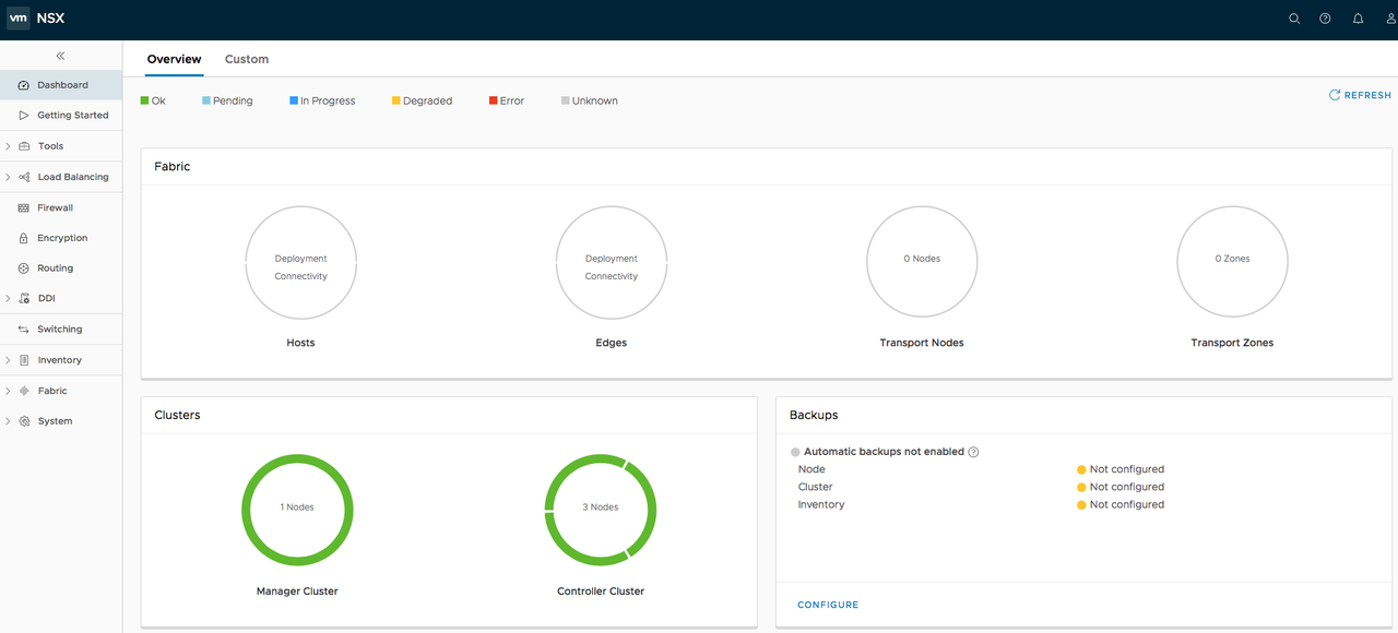
Let's now check out the GUI (you'll LOVE the NSX-T graphical interface btw):


That's it!!! Now let's go integrate it with the Hypervisors...

ACI 2018: ACI Anywhere and AVE (Application Virtual Edge)

It's 2018, and looking back at 2017 I must say that I'm quite happy, because having all in mind - it seems that Cisco is taking Cloud seriously. Four arguments to prove this:

  • Intent Based approach
  • UCS and HyperFlex evolution using Cisco Intersight
  • Cisco CloudCenter evolving
  • ACI Anywhere

Let's try and explain all these concepts...

What is Intent Based Data Center?

Apps are the new business, as our customers customer is the business developer. Intent based networking is really about building networking in accordance to that, follow the intent of the developers in the networking space. This means that what we used to call Policy, we should actually call Intent.

What is Cisco Intersight?

Cisco Intersight: The idea is to achieve the Application Continuity on the Compute level, and also on the Networking and Security level. This means that we need something to keep the coherent policies around our clouds. Intersight is a step in that direction, being the intelligent management cloud platform for Cisco Unified Computing System (UCS) and Hyper Flex

What is ACI Anywhere about?

One of the ideas of the entire Cloud native approach is to define the Policy Model, which includes Connectivity, Security and other policies, and apply the same Policy Model regardless whether your workloads are in the Public or Private cloud. In UCS we have Service Profiles, while in the ACI we have the Application Profiles. At the moment these only apply in the Data Center, where our ACI is. There are almost 4000 customers deploying ACI at the moment (January 2018). Why not extend this Policy Model to the Public Cloud? Imagine how happy the Hybrid Cloud fans, such as myself, will be when this becomes the reality.


ACI Anywhere has a simple objective: take the ACI policy model to the Cloud. The new Data Center is a Multi Cloud Data Center, so what needs to be done is a consistent management paradigm across the cloud. ACI Multi Site controller allows us to control the ACI on different sites using a single management platform, using this you can choose the Tenants that are "stretched" across multiple ACIs, and the ones that are local to some of them.

To sum up: ACI Anywhere = ACI Multi Site + ACI in Public Cloud

How do we bring ACI Policy Model to a Public Cloud? Using the AVE (Application Virtual Edge). At the moment (ACI 3.1) AVE is basically AVS. However, it will evolve into a Virtual Gateway concept that will allow us to "put" the ACI Policy Model into any Virtual Environment, and any Public Cloud. At the moment it is announced to support VMware with NSX, OpenStack, Google Cloud, AWS and Azure. Stay tuned for more details...

What about Micro Services?

Containers are the part of the new reality, because even though not many customers are actually using them at the moment - everyone is looking at them. Kubernetes is, in accordance with that, made a crucial part of ACI. I've already tested Kubernetes and OpenShift integration with ACI in my Lab, and I must say that I'm impressed. Right after the CiscoLive in Barcelona, I will cover the details of these integrations, so follow my Tweets/Blog.

OpenStack Networking, Explanation for Humans

Long time ago I published an OpenStack Networking principles, you can find it here:

Based on the feedback I got, it's too complex and hard to digest, basically - not written in a language that humans can understand. This motivated me to try and explain it in a simpler way so that anyone, even Network engineers as myself, could get it, ergo the name of the post.

OpenStack is an open source platform that is basically composed from different Projects. Networking Project is called Neutron. To fully understand how this all comes together, I will cover the following concepts:
  • Linux Networking
  • OVS (Open Virtual Switch) Networking
  • Neutron
  • Why OpenStack requires SDN.


Linux Networking
In virtualization network devices, such as Switches and NICs, are virtualized. virtual Network Interface Card (vNIC) is a NIC equivalent for a Virtual Machine (VM). Hypervisor can create one or more vNICs for each VM. Each vNIC is identical to a physical NIC (VM doesn’t "know” that its not a physical server).

Switch also can be virtualized as a virtual switch. A virtual switch works in the same way as a physical switch, it populates the CAM table that maps different Ports to MAC addresses. Each vNIC is connected to the vSwitch port, and  these vSwitch access external physical network through the physical NIC of Physical Server.

Before we get into how this all comes together, we need to clarify 3 concepts:
  • Linux Bridge is a virtual Switch used with KVM/QEMU hypervisor. Remember this, Bridge = L2 Switch, as simple as that.
  • TAP and TUN are virtual network devices based on Linux kernel implementation. TUN  works with IP packets, TAP operates with layer 2 packets like Ethernet frames.
  • VETH (Virtual Ethernet pair) is created to act as virtual wiring. To connect 2 TAPs you would need a Virtual Wire, or VETH. Essentially what you are creating is a virtual equivalent of a patch cable. What goes in one end comes out the other. It can be used to connect two TAPs that belong to two VMs from different Namespaces, or to connect a Container or a VM to OVS. When VETH connects 2 TAPs, everything that goes in on one TAP goes out on another TAP.

So, why the hell are all these concepts needed, TAP, VETH, Bridge…? These are just Linux concepts that are used to construct the Virtual Switch and give connectivity between VMs, and between VM and the outside world. Here is how it all works:
  • When you create a Linux Bridge, you can assign TAPs to it. In order to connect the VM to this Bridge, you need to then associate the VM vNIC to one of the TAPs.
  • vNIC is associated to the TAP programmatically, in software (When Linux bridge sends Ethernet frames to a TAP interface, it actually is sending the bytes to a file descriptor. Emulators like QEMU, read the bytes from this file descriptor and pass it onto the ‘guest operating system’ inside the VM, via the virtual network port on the VM. Tap interfaces are listed as part of the ifconfig Linux command, if you want to make sure everything is where it should be.)


OVS
OVS is a multilayer virtual switch, designed to enable massive network automation through programmatic extension. Linux Bridge can also be used as a Virtual Switch in a Linux environment, the difference is that the Open vSwitch is targeted at multi-server virtualization deployments where automation is used.

Open vSwitch bridge is also used for L2 Switching, exactly like the Linux Bridge, with a pretty important difference when it comes to Automation: it can operate in two modes: Normal and Flow mode.
  1. OVS in a “normal” mode, where it acts as a normal switch, learning and populating CAM table using ARP.
  2. OVS in a “flow” mode is why we use OVS and not the Linux Bridge. It lets you “program the flows”, using OpenFlow, OpFlex (whatever instructions come from the SDN controller), or manually (calling ovs-ofctl add-flow). Whatever flows are installed are used and no other behavior is implied. Regardless how the flow is configured, it has MATCH and ACTION part.  The match part of a flow defines what fields of a frame/packet/segment must match in order to hit the flow. You can match on most fields in the layer 2 frame, layer 3 packet or layer 4 segment. So, for example, you could match on a specific destination MAC and IP address pair, or a specific destination TCP port. The action part of a flow defines what is actually done on a message that matched against the flow. You can forward the message out a specific port, drop it, change most parts of any header, build new flows on the fly (For example to implement a form of learning), or resubmit the message to another table. Each flow is written to a specific table, and is given a specific priority. Messages enter the flow table directly into table 0. From there, each message is processed by table 0’s flows from highest to lowest priority. If the message does not match any of the flows in table 0 it is implicitly dropped (Unless an SDN controller is defined – In which case a message is sent to the controller asking what to do with the received packet).

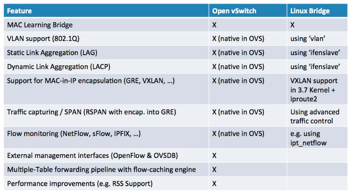
Additional differences between the Linux Bridge and the OVS are represented in the Table below:


Open vSwitch can operate both as a soft switch running within the hypervisor, and as the control stack for switching silicon (physical switch).


OpenStack Networking and Neutron

One of the mail features that OpenStack brings to the table is Multi Tenancy. Therefore, the entire platform needs to support a Multi Tenant architecture, including Networking. This means that different Tenants should be allowed to use the overlapping IP Spaces and Overlapping IP Addresses should be allowed in different Tenants. This is enabled using the following technologies:
  • Network Namespaces, which are, in a networking language, equal to the VRFs.
  • Tenant Networks are owned and managed by the tenants. These networks are internal to the Tenant, and every Tenant is basically allowed to use any IP addressing space they want.
  • Provider Networks are networks created by Administrators to map to physical network in data center. They are used to publish services from particular Tenants, or to allow OpenStack VMs (called Instances) to go out of the OpenStack Tenant environment.

To understand the concept of Provider Networks, I'll explain the two types of Provider Networks, as the only possible way of VMs to achieve the connectivity to the outside network.
  • SNAT (Source NAT) is similar to a NAT service an Office uses on a Firewall to go out to the Internet. All the VMs can use a single IP (or a group of IPs) that Admin configured when deploying OpenStack, to get to the Network outside of OpenStack environment (Internet, or a LAN network).
  • Floating IP is used for publishing services. To all the VMs you need to be accessible from the outside, you will manually need to assign a Floating IP.


Bridges and Bridge Mappings are a crucial concept when it comes to OpenStack Networking, it’s all about how different BRIDGES and TAPs come together.
  • br-int, integration network bridge, is used to connect the virtual machines to internal tenant networks.
  • br-ext, external network bridge, is used for the connection to the PROVIDER networks, to enable connectivity to and from virtual instances. Br-ext is mapped to a Physical Network, and this is where the Floating IP and SNAT IP addresses will be assigned to the instances going out from the OpenStack via the Provider Networks.

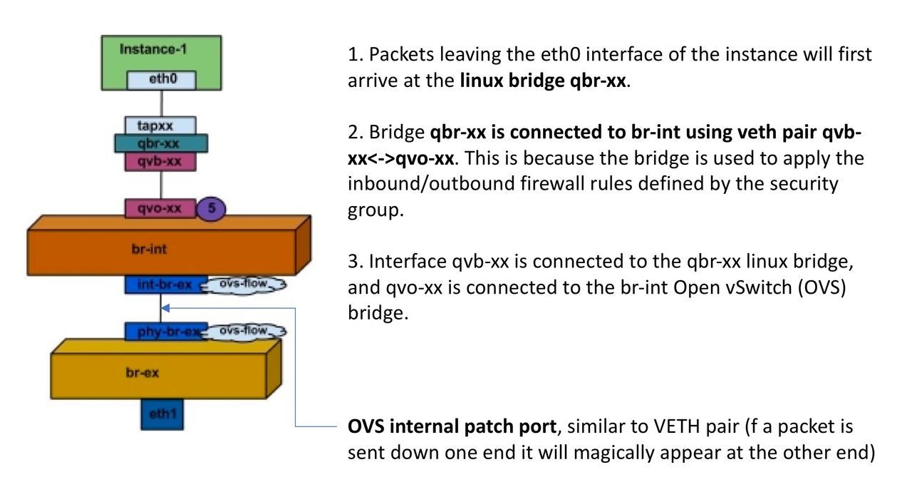
Let's check the Data Flow now, on an example of a single OpenStack instance (Instance-1) being assigned a Floating IP and accessing the Public Network.


As previously explained, a NAT is done on a br-ex, so the Floating IP is also assigned on a br-ex, and from that point on the Instance is accessing the Public Networks with the assigned Floating IP. In case the Floating IP has not been assigned, the Instance is accessing the outside world using the SNAT.


Why OpenStack requires SDN

As explained before, Neutron is an OpenStack with an API for defining network configuration. It offers multi-tenancy with self-service. Neutron uses plugins for L2 connectivity, IP address management, L3 routing, NAT, VPN and Firewall capabilities.

Here is why SDN is an essential requirement for any OpenStack production deployment:
- OpenStack cannot configure a physical network in accordance with it's needs to interconnect VMs in different Compute nodes.
- Neutron does the basic networking correctly. It cannot do routing the correct way, security policies, HA of the external connectivity, network performance management etc.
OpenStack Neutron defines services for a VM provisioning within an OpenStack deployment, these services include: NAT, DHCP, Metadata, etc.  All of these services have to be highly available and scalable to meet environment’s demands. 
SDN reduces Load on Neutron.
- Last, but not the least, I've never seen a production OpenStack deployment with no SDN. Just saying...

On PaloAlto and NSX Integration

The VM-Series firewall for VMware NSX is jointly developed by Palo Alto Networks and VMware. NetX APIs are used to integrate the Palo Alto Networks next-generation firewalls and Panorama with VMware ESXi servers. Before getting into the technical part, make sure you understand what NSX is and how micro segmentation is deployed, what the difference between the Distributed Firewall and a traditional Firewall that protects the perimeter is. You can check out some of my previous posts in the Blog Map.

The idea is to deploy the Palo Alto Networks firewall as a service on a cluster of VMware ESXi servers where the NSX has been enabled. The objective is to protect the East-West traffic in your VMware environment and "steer" the FW rules between the NSX "native" Firewall and the Palo Alto Firewall. We are doing this integration in order to be able to later enforce different type of Security Policies depending on whether we want to protect the traffic within the VMs of the same Tier (intra-tier), or between different Tiers (Inter-Tier). Best practice would be:

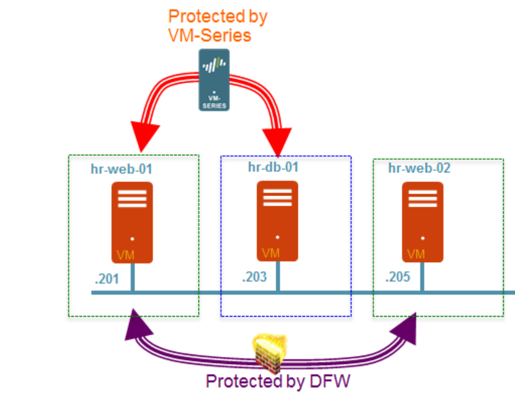
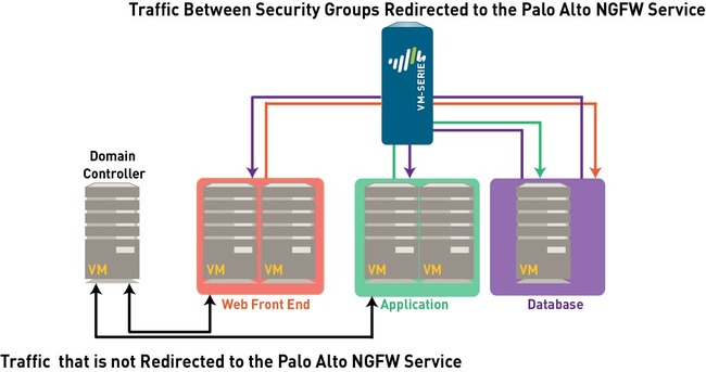
  • Inter-tier traffic (Web server to App or DB server) is protected by PaloAlto Networks VM-series  firewall which provides advanced security capabilities with its single pass architecture in the form of App-ID, Content-ID, and User-ID. On a diagram below a PA NGFW is protecting the traffic between the HRs Web and DB Servers.
  • Intra-tier traffic (web server to web server) is protected by NSX DFW which provides near line rate performance for L2-L4 security functions. On a diagram below, NSX DFW is protecting the traffic between the two HRs Web servers.

Components


Before we proceed with the detailed explanation of how to deploy and configure the environment, let's clear out what are the components of the VM-Series for NSX Solution,  how they work together and what are the benefits. The components of the integrated solution are the following:

  • vCenter Server, the centralized management tool for the vSphere suite. The vCenter server is required to manage the NSX Manager and the ESXi hosts in your data center. This joint solution requires that the ESXi hosts be organized into one or more clusters on the vCenter server and must be connected to a distributed virtual switch.
  • NSX Manager, the VMware Networking and Security platform, or simply said - SDN. The NSX Firewall and the Service Composer are key features of the NSX Manager. The NSX firewall is a logical firewall that allows you to attach network and security services to the virtual machines, and the Service Composer allows you to group virtual machines and create policy to redirect traffic to the VM-Series firewall
  • Panorama, centralized management tool for the Palo Alto NGFW (Next Generation Firewalls). In this solution, Panorama works with the NSX Manager to deploy, license, and centrally administer configuration and policies on the VM-Series firewalls for NSX. Panorama is used to register the VM-Series firewall for NSX as the Palo Alto Networks NGFW service on the NSX Manager. This allows the NSX Manager to deploy the VM-Series firewall for NSX on each ESXi host in the ESXi cluster. When a new VM-Series firewall is deployed in NSX, it communicates with Panorama to obtain the license and receives its configuration/policies from Panorama. Panorama must be able to connect to the NSX Manager, the vCenter server, the VM-Series firewalls and the Palo Alto Networks update server.
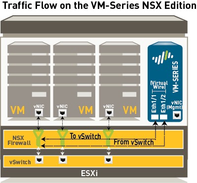
  • VM-Series Firewall for NSX (VM-100, VM-200, VM-300, VM-500, and VM-1000-HV, support NSX). The VM-Series firewall for NSX is the VM-Series firewall that is deployed on the ESXi hypervisor. The integration with the NetX API makes it possible to automate the process of installing the VM-Series firewall directly on the ESXi hypervisor, and allows the hypervisor to forward traffic to the VM-Series firewall without using the vSwitch configuration. The VM-Series firewall for NSX only supports virtual wire interfaces. On this firewall, ethernet 1/1 and ethernet 1/2 are bound together through a virtual wire and use the NetX dataplane API to communicate with the hypervisor. Layer 2 or Layer 3 interfaces are neither required nor supported on the VM-Series firewall for NSX, and therefore no switching or routing actions can be performed by the firewall.


Ports/Protocols you need to enable for the Network Communication:

  • Panorama: To obtain software updates and dynamic updates, Panorama uses SSL to access updates.paloaltonetworks.com on TCP/443; this URL leverages the CDN infrastructure. If you need a single IP address, use staticupdates.paloaltonetworks.com.
  • The NSX Manager and Panorama use SSL to communicate on TCP/443.
  • VM-Series Firewall for NSX: If you plan to use Wildfire, the VM-Series firewalls must be able to access wildfire.paloaltonetworks.com on port 443. This is an SSL connection and the App-ID is PaloAlto-wildfire-cloud.
  • The management interface on the VM-Series firewall uses SSL to communicate with Panorama over TCP/3789.
  • vCenter Server The vCenter Server must be able to reach the deployment web server that is hosting the VM-Series OVA. The port is TCP/80 by default or App-ID web-browsing.


Which version of Panorama, vSphere, NSX and PA-VM should I use?

  • Panorama: For a long time the VM-1000-HV was the only available PaloAlto VM Firewall for this integration. Don't get me wrong, it's a great option, but if cost of the solution is something that you might worry you - I've got some good news. Since Panorama 8.0 all the PA-VM versions are supported (VM-100, VM-300, VM-500 and of course VM-1000). It gets even better - you can start with the VM-100, and upgrade from there if you need more capacity in the future.
  • NSX: For my lab I used NSX 6.2.5. I recommend you go directly for 6.3.x, all the concepts explained here apply.

Integration

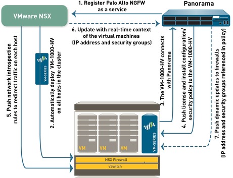
Now that we know the components, let's see how it all fits together. NSX Manager, ESXi servers and Panorama work together to automate the deployment of the VM-Series firewall, as shown in the diagram below. Lets get deeper into this...


1.1 Install the VMware NSX Plugin

Before you start the integration, you need to make sure that your NSX is operational, NSX Controllers in the "Connected" state (vSphere > NSX > Installation > Management). I strongly advise you to upgrade your Panorama to 8.0.x, if you haven't already. In my Lab I used only 2 hosts at first. Once I had everything fully functional, I added the other hosts.


You need to Download the Plugin from here (you will need a Palo Alto Support account):
https://support.paloaltonetworks.com/Updates/SoftwareUpdates/1904

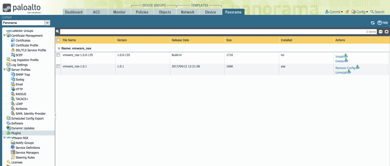
Log in to Panorama, and go to "Panorama Tab > Plugins". Upload the Plugin, and press "Install". A new "VMware NSX" sub-menu will appear on the left, as shown below.


Next you need to set up access to the NSX Manager. Select Panorama > VMware NSX > Service Managers and click Add. Enter the Service Manager Name and the other required info. If you do this step correctly, on the NSX Manager, this name will be displayed in the Service Manager column on Networking & Security > Service Definitions > Service Managers.

IMPORTANT: The ampersand (&) special character is not supported in the NSX manager account password. If a password includes an ampersand, the connection between Panorama and NSX manager fails.

TIP: Once the Services are Synchronized, in PANOS 8.0 you won´t be able to see the Service Manager Status. Don´t panic, this is Ok. As long as you see the new Service Manager has been configured in NSX (Networking & Security > Service Definitions > Service Managers) - you´re good to go.

In Panorama you will also see a new Administrator user called "__vmware_nsx" has been configured. In NSX try to edit the newly created "Service Manager". You will notice that the credentials are associated to this new user.

1.2 Create Template(s) and Device Group(s) on Panorama

To manage the VM-Series firewalls for NSX using Panorama, the firewalls must belong to a device group and a template. Device groups allow you to assemble firewalls that need similar policies and objects as a logical unit; the configuration is defined using the Objects and Policies tabs on Panorama. Use templates to configure the settings that are required for the VM-Series firewalls to operate on the network and associate; the configuration is defined using the Device and Network tabs on Panorama (Groped as Templates). And each template containing zones used in your NSX configuration on Panorama must be associated with a service definition; at a minimum, you must create a zone within the template so that the NSX Manager can redirect traffic to the VM-Series firewall.

Go to Panorama > Device Groups, and click Add. Name your Device Group something Intuitive, like NSX Firewalls. After the firewalls are deployed and provisioned, they will display under Panorama > Managed Devices and will be listed in the device group.

Now add a template or a template stack. Select Panorama > Templates, and click Add. After this you need to create the Zone for each template (be sure to set the interface Type to Virtual Wire.). Panorama creates a corresponding service profile on NSX Manager for each qualified zone upon commit.

IMPORTANT: For a single-tenant deployment, create one zone. If you have multi-tenant deployment, create a zone for each sub-tenant.

Now you need to add a new Service Definition. This is basically used for Panorama to know how to provision a PaloAlto Firewall on the Hosts where it is needed. Select Panorama > VMware NSX > Service Definitions.

TIP: Before you define the Service Definition, you need to place your PA-XXX.ova file on a Web Server. I know, not as cool as the Architects of the solution imagined it, but still... it´s logical that Panorama needs an Image Repository with different types of PA-VM, because a big environment might require a variety of different Firewalls.

Once the Service Definition is created, Select Panorama > VMware NSX > Service Manager and click the link of the service manager name. Under Service Definitions, click Add and select your service definition from the drop-down.

Now you need to Add the authorization code to license the firewalls. I hope you already have the Auth Code by now. Select Panorama > Device Groups and choose the device group you associated with the service definition you just created. Under Dynamically Added Device Properties, add the authorization code you received with your order fulfillments email and select a PAN-OS software version from the SW Version drop-down. When a new firewall is deployed under NSX and added to the selected device group, the authorization code is applied and the firewall is upgraded to the select version of PAN-OS.

IMPORTANT: You need to Install a License Deactivation API Key in Panorama before you proceed with the FW Deployment in the ESXi Cluster. This is important before you want your Panorama to take care of the Licenses using the Auth-Code.

admin@Panorama> request license api-key set key bea265bdb4c832793b857cfa1bf047845dc82e3b3c1b18c1b2e59796147340eb

API Key is successfully set
admin@Panorama>

2. Register the VM-Series Firewall as a Service on the NSX Manager

2.1 The first step is to register the Palo Alto Networks NGFW as a service on the NSX Manager. The registration process uses the NetX management plane API to enable bi-directional communication between Panorama and the NSX Manager. Panorama is configured with the IP address and access credentials to initiate a connection and register the Palo Alto Networks NGFW service on the NSX Manager. The service definition includes the URL for accessing the VM-Series base image that is required to deploy the VM-Series firewall for NSX, the authorization code for retrieving the license and the device group and template to which the VM-Series firewalls will belong. The NSX manager uses this management plane connection to share updates on the changes in the virtual environment with Panorama.

2.2 Deploy the VM-Series automatically from NSX —The NSX Manager collects the VM-Series base image from the URL specified during registration and installs an instance of the VM-Series firewall on each ESXi host in the ESXi cluster. From a static management IP pool or a DHCP service (that you define on the NSX Manager), a management IP address is assigned to the VM-Series firewall and the Panorama IP address is provided to the firewall. When the firewall boots up, the NetX data plane integration API connects the VM-Series firewall to the hypervisor so that it can receive traffic from the vSwitch.


2.3 Establish communication between the VM-Series firewall and Panorama : The VM-Series firewall then initiates a connection to Panorama to obtain its license. Panorama retrieves the license from the update server and pushes it to the firewall. The VM-Series firewall receives the license (VM-1000-HV) and reboots with a valid serial number.

2.4  Install configuration/policy from Panorama to the VM-Series firewall : The VM-Series firewall reconnects with Panorama and provides its serial number. Panorama now adds the firewall to the device group and template that was defined in the service definition and pushes the configuration and policy rules to the firewall. The VM-Series firewall is now available as a security virtual machine that can be further configured to safely enable applications on the network.

2.5 Push traffic redirection rules to NSX Manager : On Panorama, create security groups and define network introspection rules that specify the guests from which traffic will be steered to the VM-Series firewall. See Integrated Policy Rules for details.

2.6 Receive real-time updates from NSX Manager : The NSX Manager sends real-time updates on the changes in the virtual environment to Panorama. These updates include information on the security groups and IP addresses of guests that are part of the security group from which traffic is redirected to the VM-Series firewall. See Integrated Policy Rules for details.

2.7 Use dynamic address groups in policy and push dynamic updates from Panorama to the VM-Series firewalls : On Panorama, use the real-time updates on security groups to create dynamic address groups, bind them to security policies and then push these policies to the VM-Series firewalls. Every VM-Series firewall in the device group will have the same set of policies and is now completely marshaler to secure the SDDC. See Policy Enforcement using Dynamic Address Groups for details.

3. Create Steering Rules

IMPORTANT: The default policy on the VM-Series firewall is set to deny all traffic, which means that all traffic redirected to the VM-Series firewall will be dropped. Have this in mind before you activate PA NGFW in your VMware environment.

Panorama serves as the single point of configuration that provides the NSX Manager with the contextual information required to redirect traffic from the guest virtual machines to the VM-Series firewall. The traffic steering rules are defined on Panorama and pushed to NSX Manager; these determine what traffic from which guests in the cluster are steered to the Palo Alto Networks NGFW service. Security enforcement rules are also defined on Panorama and pushed to the VM-Series firewalls for the traffic that is steered to the Palo Alto Networks NGFW service.

Steering Rules —The rules for directing traffic from the guests on each ESXi host are defined on Panorama and applied by NSX Manager as partner security services rules.


For traffic that needs to be inspected and secured by the VM-Series firewall, the steering rules created on Panorama allow you to redirect the traffic to the Palo Alto Networks NGFW service. This traffic is then steered to the VM-Series firewall and is first processed by the VM-Series firewall before it goes to the virtual switch.

Traffic that does not need to be inspected by the VM-Series firewall, for example network data backup or traffic to an internal domain controller, does not need to be redirected to the VM-Series firewall and can be sent to the virtual switch for onward processing.

Rules centrally managed on Panorama and applied by the VM-Series firewall —The next- generation firewall rules are applied by the VM-Series firewall. These rules are centrally defined and managed on Panorama using templates and device groups and pushed to the VM-Series firewalls. The VM-Series firewall then enforces security policy by matching on source or destination IP address—the use of dynamic address groups allows the firewall to populate the members of the groups in real time—and forwards the traffic to the filters on the NSX Firewall.

Policy Enforcement using Dynamic Address Groups

Unlike the other versions of the VM-Series firewall, because both virtual wire interfaces (and subinterfaces) belong to the same zone, the VM-Series firewall for NSX uses dynamic address groups as the traffic segmentation mechanism. A security policy rule on the VM-Series firewall for NSX must have the same source and destination zone, therefore to implement different treatment of traffic, you use dynamic address groups as source or destination objects in security policy rules.

Dynamic address groups offer a way to automate the process of referencing source and/or destination addresses within security policies because IP addresses are constantly changing in a data center environment. Unlike static address objects that must be manually updated in configuration and committed whenever there is an address change (addition, deletion, or move), dynamic address groups automatically adapt to changes.

Any dynamic address groups created in a device group belonging to NSX configuration and configured with the match criterion _nsx_ trigger the creation on corresponding security groups on the NSX Manager. In an ESXi cluster with multiple customers or tenants, the ability to filter security groups for a service profile (zone on Panorama) on the NSX Manager allows you to enforce policy when you have overlapping IP addresses across different security groups in your virtual environment.

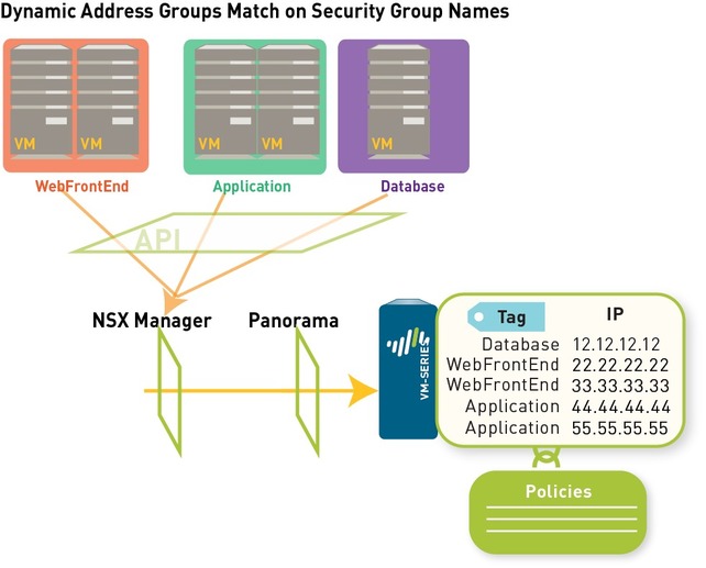
If, for example, you have a multi-tier architecture for web applications, on Panorama you create three dynamic address groups for the WebFrontEnd servers, Application servers and the Database servers. When you commit these changes on Panorama, it triggers the creation of three corresponding security groups on NSX Manager.


CONCLUSION: Panorama Dynamic Address Group = NSX Security Group

On NSX Manager, you can then add guest VMs to the appropriate security groups. Then, in security policy you can use the dynamic address groups as source or destination objects, define the applications that are permitted to traverse these servers, and push the rules to the VM-Series firewalls.

Each time a guest is added or modified in the ESXi cluster or a security group is updated or created, the NSX Manager uses the PAN-OS REST-based XML API to update Panorama with the IP address, and the security group to which the guest belongs.

When Panorama receives the API notification, it verifies/updates the IP address of each guest and the security group and the service profile to which that guest belongs. Then, Panorama pushes these real-time updates to all the firewalls that are included in the device group and notifies device groups in the service manager configuration on Panorama.

On each firewall, all policy rules that reference these dynamic address groups are updated at runtime. Because the firewall matches on the security group tag to determine the members of a dynamic address group, you do not need to modify or update the policy when you make changes in the virtual environment. The firewall matches the tags to find the current members of each dynamic address group and applies the security policy to the source/destination IP address that are included in the group.

Is this a Multi Tenant environment? For enabling traffic separation in a multi-tenancy environment, you can create additional zones that internally map to a pair of virtual wire sub-interfaces on the parent virtual wire interfaces, Ethernet 1/1 and Ethernet 1/2.
Nuage Networks VSP Deep Dive

Ever since Cisco bought Insieme and created Cisco ACI, and VMware bought Nicira and created NSX, I've been intensively deep-diving and blogging about both these solutions, how they compare to each other and to some Open Source SDN solutions out there, such as OpenDayLight and Open Contrail |(check out the Blog Map section for some of my older posts). I even did boot camps and got the highest certifications in both NSX and ACI. SDN is still a rather new technology, and I wanted to make sure I have enough expertise to always explain to a customer which SDN solution is the right one for their Organization and why. Apart from ACI, NSX and open source solutions, there is another player on the SDN market, and from what I've seen - they mean business! I'm talking about Nuage Networks, acquired by Nokia from Alcatel-Lucent in November 2016. Even though I've known about this solution for a while, my opinion was that their strongest side was marketing, so I didn’t spend a lot of time investigating about Nuage (it's also pretty difficult to find the information about Nuage, there is an apparent lack of experts/blogs/technical info about the product). I finally decided to give them an opportunity, I did a boot camp, a lots of Hands-on, and recently I passed a certification 4A0-N01 Nuage Network Professional – Datacenter (NNP-DC). Let me share with you what Nuage Networks is all about, and give the unbiased opinion about their understanding of SDN, and how they compare to other SDN solutions on the market.

Disclaimer: Some of the materials I used come directly from Nuage technical documentation, which is for some reason not available to the public (and it should be!). If someone from Nokia is reading this, please note that revealing technical information about what your product provides more market, and gives more visibility to your product. I strongly advise you to make as much Nuage documentation public as possible, because if your product is good (and in my opinion - it is), invite bloggers and technical experts to give you feedback, if they feel comfortable with your product, they will feel free sharing it with potential customers.

Before I get deeper into what Nuage VSP is good for, let's make sure we understand the difference between the IaaS, PaaS and SaaS. In order to really get what your company is doing (or should be doing), whether you are a Service Provider (SP), or an Enterprise consuming resources provided by other Service Provider, you need to have a clear distinction of what is handled by whom in each of these architectures. Basically:

  • IaaS (Infrastructure as a Service) - SP Provides Network, Compute and Storage, Customer builds OS and Apps
  • PaaS (Platform as a Service) - SP also Provides the OS. Who takes tare of the OS Upgrades and other stuff? Good questions… Depends on the PaaS Provider, could be either way.
  • SaaS (Software as a Service) - SP owns everything, including the application

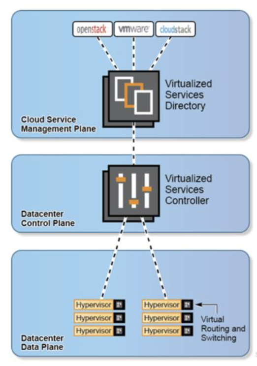
Let's start with the basics. We already know what SDN is all about, separating the Control Plane from the Data Plane, and providing a single Management plane that exposes the Northbound APIs. Nuage  follows the same concepts. Nuage created a platform called VSP. VSP  stands for Virtualized  Services Platform, and it does the Orchestration of the Deployment, handling  the following Planes:

  • Management plane, represented by Nuage Virtual Service Directory (VSD) and the Cloud Management System or CMS (OpenStack, CloudStack etc.)
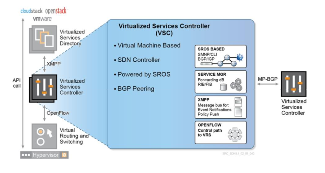
  • Control plane, handled by Nuage Service Controller (VSC)
  • Data Plane, handled by a Virtual Router & Switch (VRS)


VSP includes the software suite comprising of three key products:

  • VSD (Virtual Services Directory), which holds the policy and network service templates.
  • VSC (Virtual Services Controller), which is the SDN controller that communicates to the hypervisors.
  • VRS (Virtual Routing and Switching) agent that resides within the hypervisor on the server hardware.

Let's now take a deep dive into what communication protocols are deployed between different VSP components:

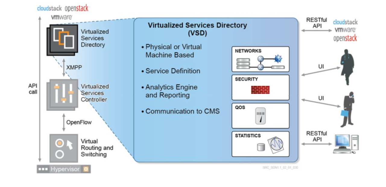
  • Communication between the CMS (Cloud Management System, such as OpenStack, CloudStack, vCenter, vCloud, etc.) and the VSD is done via RESTful APIs. We're talking about the Northbound APIs that allow us to configure Nuage Platform, or VSP.
  • Communication between the VSD and VSC is via industry standard XMPP (Extensible Messaging and Presence Protocol), using the Management network. SSL is optional, but recommendable.
  • Communication between the VSC and the hypervisors (including the VRS) is via OpenFlow, using the Underlay Network. SSL is again, optional but recommended.
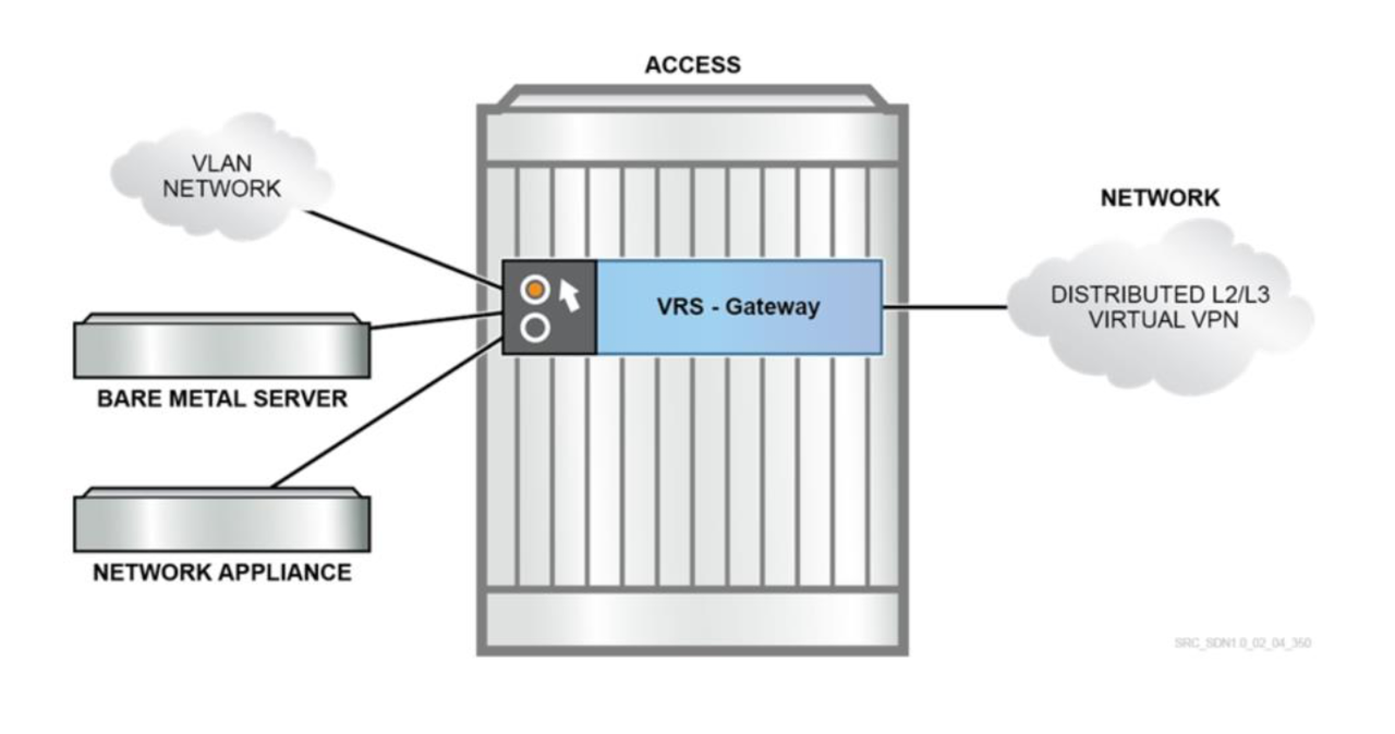
  • SDN is all about virtualization, but luckily - physical servers have not been forgotten. To integrate “bare metal” assets such as non-virtualized servers and appliances, Nuage Networks also provides a comprehensive Gateway solution: software-based VRS gateway (VRS-G) and hardware-based 7850 VSG.

I'd recommend you to get acquainted with the individual components of the architecture by reading the rest of this post first, and then re-visit the previous paragraph. It will all make much more sense for you.

Let's now check out individual Nuage VSP components, and see what each one does. Once again, I'll try to be methodical (not an intuitive task for my mind), and try to structure the post, so that you can follow:

  1. VSD, or the Virtualized Services Directory at the Network Management Plane
  2. VSC, or the Virtualized Services Controller, at the Network Control Plane
  3. VRS and VSG , or the Virtualized Routing & Switching and Virtualized Services Gateway, at the network Data Plane
  4. Security Policies: NFV and Service Chaining


1. VSD  - Virtualized Services Directory, holds the Policy and Network Templates. VSD uses XMPP protocol to communicate with VSC.

VSD is where we do the Service Definition by defining Network Service Templates. The service definition includes domain, zone, subnet and policy templates. A domain template can also include policies (e.g. security, forwarding, QoS, etc.) to be applied at the different levels (vPort, subnet, zone, domain). I will cover all these concepts in just a while. It´s an essential component that will manage everything. It can be deployed as a Physical or a Virtual machine. it comes as an OVA file (for ESXi) and QCOW2 file (for KVM), or as an ISO image (recommended for the production environment). You can choose whether you want to do a standalone deployment, or a cluster of 3 VMs. To work properly, VSD requires an NTP server and a DNS server in the network.


The VSD also contains a powerful analytics engine (optional, based on Elastic Search). The VSD supports RESTful APIs for communicating to the cloud provider’s management systems. In the case of OpenStack, it is between nova and nova-compute, while vCloud uses the vCenter API to access the ESXi HVs.

VSD has two types of users:
Administrator/CSP Users, who will have full visibility into all of the functionality of VSD
Enterprise/Organization Users. An enterprise user belongs to one, and only one, specific enterprise.

TIP: Have in mind that if you're interesting in LDAP, users must be manually created in VSD, even if they have already been created in the LDAP directory.

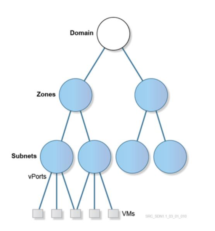
VSD Service Abstraction - a VSD way of creating an Object Tree, where the Domain is the one Root and Zones, Subnets and another Object have an exact place in the Tree. VSD then translates the Service Abstraction into the Service Instances, following the same Object Tree. Having in mind that domain is mapped to a distributed VPRN instance (dVPRN) while a subnet is mapped to a distributed RVPLS instance (dRVPLS), we are counting with:

  • L2 Service Instances (vRVPLS)
  • L3 Service Instances (dRVPN)


Domain:  An enterprise contains one or more domains. A domain is a single “Layer 3” space, which can include one or more subnetworks that can communicate with each other. In standard networking terminology, a domain maps to a VPRN (Virtual Private Routed Network) service instance. Route distinguisher (RD) and route target (RT) values for the VPRN service are generated automatically by default, but can be modified. CSP Root users can create domain template for all the enterprises. Enterprise Administrators and Network Designers group users can create domain templates for their enterprises. Users that belong to other groups cannot create domain templates.
Layer 2 Domain:  A standard domain is a Layer 3 construct, including routing between subnets. A Layer 2 domain, however, is a mechanism to provide a single subnet, or a single L2 broadcast domain within the datacenter environment. It is possible to extend that broadcast domain into the WAN, or legacy VLAN.
Zone:  Zones are defined within a domain. A zone does not map to anything on the network directly, but instead it acts as an object with which policies are associated such that all endpoints in the zone adhere to the same set of policies.
Subnet: Subnets are defined within a zone. A subnet is a specific IP subnet within the domain instance. The subnet is instantiated as a routed virtual private LAN service (R‐VPLS). A subnet is unique and distinct within a domain; that is, subnets within a domain are not allowed to overlap or to contain other subnets in accordance with the standard IP subnet definitions.
vPorts: Intended to provide more granular configuration than at the subnet level, and also support a split workflow. The vPort is configured and associated with a VM port (or gateway port) before the port exists on the hypervisor or gateway. Ports that connect the Bare Metal Servers to an Overlay are also called vPort. Whenever an vPort is instantiated, an IP address is assigned to it, unique at the Domain level, from the Subnet that the vPort belongs to. VSD is responsible for assigning the correct IP address, regardless if the VM asks for a specific IP (statically configured on the OS), or from a DHCP pool. The same Virtual IP can be assigned to multiple vPorts for redundancy (must be different then any of the IPs assigned to the vPorts).
All ports will have a corresponding vPort, either auto-configured or configured via REST API. Configuration attributes may optionally be configured on the vPort.

VM is formed from its profile, which contains the VM metadata. This metadata defines which Domain, Zone, Subnet and vPort to apply to every vNIC of the VM. It also defines which Enterprise and User Group it belongs to.  Additionally, some metadata may be specified if attaching to a specific vPort is required. When a new VM is created, a VM creation request is sent to the VSC from the VRS agent in an OpenFlow message using the Underlay Network. This message contains the VM-related metadata. VSC forwards the request one level higher in the hierarchy, to the VSD in an XMPP message using the Management Network. The VSD receives the VM creation request, reads its metadata and checks them against the policy definitions. The VSD learns the MAC address assigned to this VM from the metadata, and in a VSD managed IP address allocation scenario, it assigns an IP address for it from the subnet (usually the next available IP address).

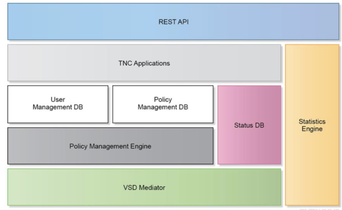
VSD has a somewhat complex architecture. The components of the VSD can be centralized on a single machine or distributed across multiple machines for redundancy and scale. Some of the most important to have in mind at this point are:

  • TNC stands for trusted network connect, which is an open architecture for network access control.
  • Policy management engine evaluates the policy rules configured on the VSD (Security and QoS policies, IP assignments etc.) It sends policies to VSC based on network events.
  • VSD mediator is a VSD Southbound interface used for communication to the VSC. It receives requests for policy information and updates from the VSC, and pushes policy updates to the VSC. The VSD itself is an XMPP client: it communicates with an XMPP server, or server clusters.
  • Statistics engine collects fine-grained network information at the VRS, VSC and VM levels. It can collect various packet-based statistics such as Packets in/out, dropped packets in/out, dropped by rate limit etc. It provides an open interface for Nuage and third-party analytics applications. Have in mind that by default, Statistics collection is disabled on the VSD. A separate VSD node running Elastic Search needs to be deployed (can also be deployed as a Cluster).
  • REST API is the VSD Northbound interface, which exposes all the VSD functionalities via API calls. It can be used by Nuage CMS plug-ins for integration with many CMSs.


2. VSC - Virtualized Services Controller - SDN Controller, controls the Network, communicates with the Hypervisor and collects the VM related information such as MAC and IP addresses . VSC uses OpenFlow to control the VRS. On each VRS we need to define which VSC is active, and which is standby (you can configure various active VCS for Load Balancing). OpenFlow uses TCP port 6633, and it is used to download actual L2/L3 FIBs to the virtual switch components on the Hypervisor.


VSC is only installed as a VM (or as an Integrated Module on a Nuage NSG, when NSG is used as VxLAN Gateway), and it comes as OVA file, a QCOW2 file and a VMDK file. VSC has a control interface connected to the Underlay. It is based on Nokia Service Router Operating System (SROS), which is somewhat similar to Cisco IOS (not the same commands, but… intuitive, if you come from Cisco).

Now comes a really cool part about why Nuage. Controllers act like Router Control Plane, and routing is established between VSCs and other routers. This makes is so much easier to implement DCI. VSC needs a routing protocol to exchange the routes with the other VSCs. It can be ISIS, OSPF or Static Routes. MP-BGP EVPN also needs to be established between all the VSCs.

The VSC has three main communication directions:
Northbound: to the VSD via XMPP
East/West: federation functions to other VSCs or IP/MPLS Provider Edge nodes via MP-BGP
Southbound: to the VRSs via OpenFlow

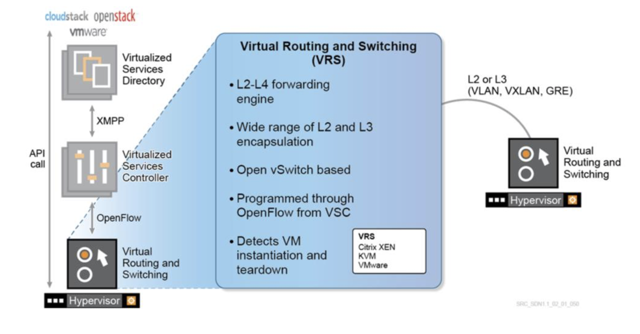
3. VRS (Data Plane) - Virtual Routing and Switching plugin inside the Hypervisor. It´s based on OVS, and it´s responsible for L2/L3 forwarding, encapsulation.

 On VRS you can define various VSC for redundancy and load balancing (one active and one standby), and each of them establishes an OpenFlow session using the Underlay network, not Management , using TCP port 6633 (SSL is optional).

VRS includes two main Nuage components:

  • VRS Agent, that talks to VSC using OpenFlow. It's responsible for programming L2/L3 FIBs, and it replies to all ARP (no flooding). It also reports changes in VMs to the VSC. The forwarding table is pushed to VRS from VSC via OpenFlow. It has not only a view of all the IP and MAC addresses of the VMs being served by the local hypervisor, but also those which belong to the same domain (L2 and L3 segments), that is, all possible destinations of traffic for the VMs being served by that HV.
  • Open vSwitch (OVS), provides Switching and Routing components and Tunneling to forward the traffic.

VRS supports a wide range of L2 and L3 encapsulation methods (VXLAN, VLAN, MPLSoGRE) so that it can communicate with a wide range of external network endpoints (other hypervisors, IP- or MPLS-based routers).


Let's get even deeper into the connection between the Control Plane and Data Plane, or VSC and VRS in Nuage Language. Nuage Networks uses Open Source components, such as libvert, OVS and OpenFlow. Nuage Networks makes use of the libvirt library in the VRS component that runs in Linux-based hypervisor environments (Xen and KVM) to get VM event notifications (new VM, start VM, stop VM, etc.). Libvirt is a package installed on the Hypervisor. Nuage also installs Nuage VRS. This enables the usage of User space tools:

  • Virt-Manager: For GUI
  • Virsh: Commands (CLI)

Before we continue, let's make sure we understand the basic concepts needed to understand the VRS and VGS (VRS-G included). Basically we need to understand:

  • What is OVS (Open virtual Switch).
  • Difference between the Underlay and the Overlay.
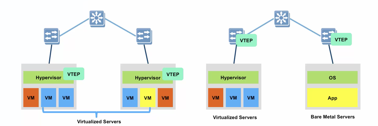
  • What is VxLAN, what are VTEPs, and how it all works.

Open vSwitch (OVS) is a major building block for Nuage SDN. It implements a L2 bridge includingu MAC learning. . OpenFlow is used to configure the vSwitch. It's used for Linux Networking and it's part of Linux Kernel, now used instead of Linux Bridge. OVS can be configured via CLI, OpenFlow or OVSDB management protocol. OVS doesn’t work like VMware VDS or Cisco 1000v. Instead, it only exists on each individual physical host, and it makes it easier for developers of virtualization/cloud management platforms to offer distributed vSwitch capabilities. In Nuage, OpenFlow is used to program the virtual switch within the hypervisor, with the vSwitch becoming the new edge of the datacenter network. The OVS becomes the access layer of the network. The access is where control policies are typically implemented: ACLs, QoS policies, monitoring (netflow, sflow), OVS has these features, and also provides an SDN programmatic interface (OpenFlow and OVSDB management).

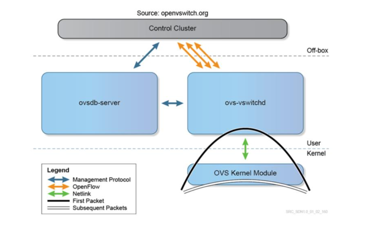
The three main components of OVS are:

  • ovsdb-server is the configuration database which contains details about bridges, interfaces, tunnels, QoS, etc.
  • OVS kernel module handles the data path, including packet header handling, table lookup and tunnel encapsulation and decapsulation. The first frame of a flow goes to ovs-vswitchd to make the forwarding decision; the following frames are then processed by the kernel.
  • ovs-vswitchd matches the first frame for a “flow” action (L2 forwarding, mirroring, tunneling, QoS processing, ACL filtering, etc.) and caches these in the flow table in the kernel module.


The Open vSwitch is configured by the “control cluster” through a combination of the following methods:

  • SSH and the CLI can be used to manually configure the switch locally
  • The OVSDB management protocol is used to create switch instances, attach interfaces and define QoS and security policies.
  • OpenFlow is used to establish flow states and the forwarding tables for these flows
  • Netlink is the Linux communication API used between kernel and user space

Open vSwitch can also be implemented on hardware switches, for example an SDN white box switch, as OVSDB management protocol is also implemented on some vendors’ switches.

Overlay Network: Virtual abstraction built on top of a Physical Network. There are Network-Centric overlays (VPLS, TRILL, Fabric Path) where hosts are not aware of the Overlay, and Host-Centric (VxLAN, NV-GRE, STT) where hosts help create the virtual tunnels.

VxLAN: You can check out my previous posts (go to Blog Map) for more details on how VxLAN Control Plane and Encapsulation take place. VXLAN has a 24 bit VXLAN identifier, which allows for 16 million different tenant IDs. The VXLAN UDP source port is set on the sending side with a special hashing function that allows for load balancing of traffic by ECMP (equal cost multiple path) in the datacenter network. Destination Port is 4789. On the data plane, each VTEP capable device needs to have a forwarding table with each possible destination MAC address within the same L2 domain and the hypervisor hosting it. The VNI identifies the L2 domain within the DC.

More and more server NIC cards support VXLAN offload functionality, which improves the encapsulation/decapsulation performance.

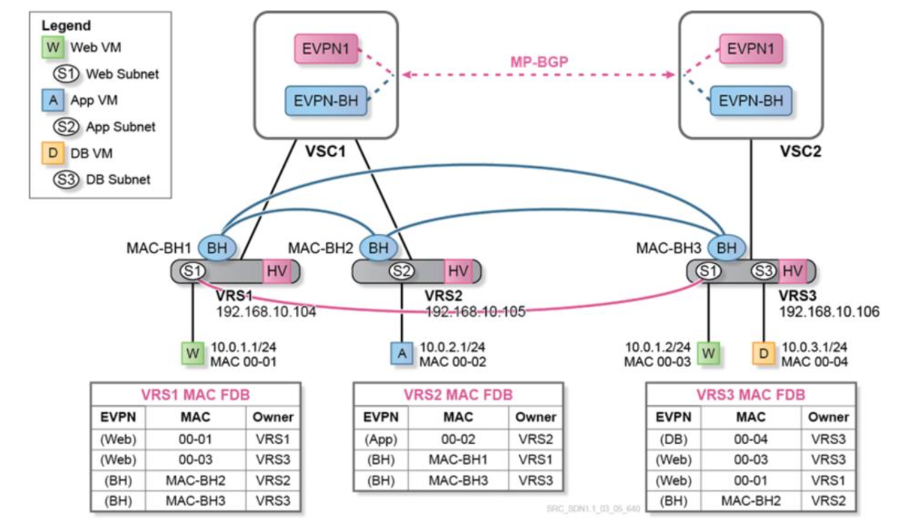
All VTEPs (Virtual Tunnel End Points) in the VxLAN Control Plane need at least the IP connectivity. VTEP needs to act as the default gateway for all the subnetworks that its hosted VMs belong to. In order to do this, VTEP will be assigned a MAC address and an IP address within each of such subnetworks. The combination of the IP and MAC addresses corresponding to a given VM is known as EVPN prefix. When a packet is sent by a VM to its default gateway, because its final destination is an IP address in a different subnetwork, the VTEP will look into its EVPN route table, swap the destination MAC address (presently pointing to the default gateway) to the MAC address of the VM intended to receive the packet, and send the frame to the VTEP hosting the destination VM using the corresponding VXLAN tunnel.

BGP EVPN is an Address Family that can include both, IP and MAC address for a given end point. Forwarding tables on each hypervisor contain information about all VMs in all subnets (each subnet corresponds to a different EVPN instance). VXLAN tunnels exist to reach these subnets on all the hypervisors. Backhaul VPLS brings optimization and enhanced scaling for the number of EVPN MAC addresses and tunnels. With this optimization, each VRS receives only complete forwarding information related to subnets (EVPNs) locally hosted on itself. Each VRS is still aware of every VM in remote subnets, the hypervisor hosting it and its IP address (but not its MAC address). Consequently, when a VM wants to communicate with another VM in a remote EVPN, the VRS (acting as the default gateway) only has to do a route-table lookup to identify which hypervisor is hosting the relevant IP address. This way, it can use the VXLAN tunnel indicated by the backhaul VPLS to forward the packet. There is no need in this case to find the corresponding VPLS and to do an additional L2 FDB lookup to determine the destination MAC address, as would happen if the subnet were not remote.


VRS is in the Underlay Network, and OVS is in the Overlay Network. All Hypervisors need at lease one interface connected to the Underlay Network. You can also have the VTEP assigned to the ToR Switch instead of a Hypervisor, but the concepts don't change.


VSG - Virtual Services Gateway allows the interconnection between Physical and Virtual domains. It basically translates VLAN to VxLAN (VxLAN towards Nuage Overlay, and VLAN to Legacy Infrastructure). There are two Nuage versions (physical and virtual), and a version for the "White Boxes":

  • Software (VRS-G) which offers Network ports via Overlay (VxLAN) and access ports to the traditional network (VLAN)
  • Hardware, 7850 VSG is a 10/40G  Switch providing VTEP GW functionality (VTEP in Hardware).
  • Hardware VTEP on a White Box


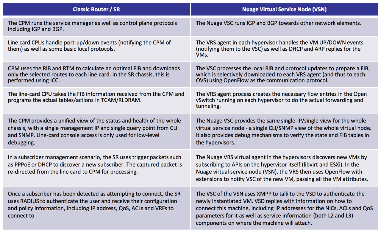
VSN is a Virtual Service Node, composed of VSC and a group of VRS. VSC is like a Control Plane, and VRS are like a Hypervisors. The VSN provides the network operator with a unified view of all the elements being handled by it, making HVs appear as line cards in a chassis when compared to a classic router. It provides a one-stop management and provisioning point for all the HVs under the VSN control.


4. Don’t forget the Security: NFV and Service Chaining

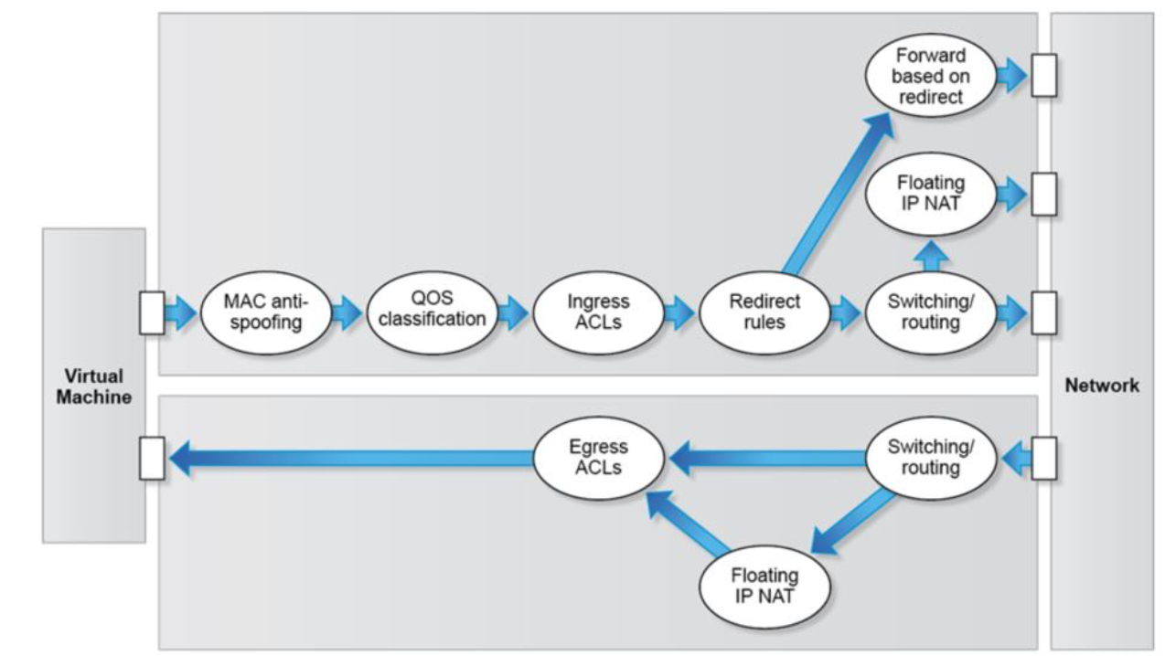
Security Policies are defined at a Domain level, define From/To Zones and/or Subnets. It is important to understand the relative directions of security policies before implementing them. The easiest way to understand the directions is to imagine it from the OVS point of view. This would mean that the INGRESS would me traffic entering the OVS, and Egress - traffic going OUT of the OVS:
Ingress refers to the direction of traffic flow from the VM towards the network (or the OVS component).
Egress refers to the direction of traffic from the network (or the OVS component) towards the VM

Policies have priorities which allows defining the order. They can be Imported/Exported between the Domains, or to/from a File. Before you apply the policies:
By default all INGRESS traffic is dropped (INGRESS means from VM to the OVS).
By default all EGRESS traffic is accepted (from OVS to VM).

When defining the Security Policy, it's important to have in mind Nuage mode of operation, shown on the diagram below.


At the time of creation, a Policy Group Type is assigned to each Security Policy:
Hardware, for hosts and bridge vPort hosted in Nuage VSG/VSA Gateways
Software, VRS and VRS-G hosted vPort, including VM, host and bridge vPort

Important: When you do Stateless, you need ACLs for "returning" traffic. For stateful you just need one policy in one direction.

ACL Sandwich feature enables a network admin to define a supra-list that will drop specific traffic that should NEVER reach the VM. The end user who owns the domain instance can then combine ACL rules into ACLs defined on the domain instance level.

Logging can be able on ACL entry level.

Service Chaining
VSP provides so called Forwarding Policies to control the redirection of packets. This is what later enables Service Chaining. In my opinion, Nuage has the most elegant implementation of Service Chaining of all SDN products out there. All is implemented through flow-based redirection.

Nuage supports Physical and Virtual L4-7 Appliances/Cluster of Appliances as redirection targets, and it gives you the option of creating the Advanced Redirection Policies, where you're given the option to redirect only the traffic destined to a certain TCP/UDP port.

Most Popular Posts